Keyboard and IR Blaster Fabrication Guide
This guide focuses on recreating the project as we delivered it to UCPLA as the final prototypes for the 2020 Hackaday Prize UCPLA Dream Team.
Table of Contents
Product Summary
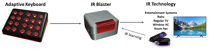
The Adaptive Universal Remote comprises of 2 products:
- Universal IR Blaster
- Adaptive Keyboard
They keyboard and IR blaster communicate using the ESP-NOW WiFi protocol. The keyboard is configured to send commands to one specific IR blaster. The IR blaster stores and sends IR codes when instructed to do so from the keyboard. They keyboard simply forwards commands per key to the IR blaster. They IR blaster can be pre-configured to work with any device that accepts IR commands. The commands can also be changed by the user using the learning feature.
IR Blaster
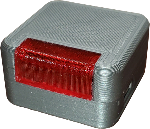
Dimensions: 43mm x 43mm x 25mm Control Range: 2.5m
Cost: ~$35.00
Assembly Time: 30 min
3D Print Time: 4 hrs
You can find the BOM in the IR Blaster Hardware Readme.
IR Blaster Enclosure
Since this part takes the longest it is placed first.
IR Blaster Hardware
Review the IR Blaster Hardware Readme for an overview of the parts and schematics.
Equipment Needed:
- Soldering Iron
- Solder
- Wire Strippers
- Wire Cutters
- Wire (8 mm)
IR Blaster Assembly:
- Solder the IR receiver and transmitter to the IR blaster. See the Sparkfun WiFi IR Blaster Hookup Guide - Hardware Overview for more details.
- To prep the red LED, place a 90 degree bend at the end of the cathode so that 5mm of are perpendicular to the LED.
- Place the red LEDs anode into pin 2 of the IR blaster, and set the cathode over the GND pin.
- Then solder the red LEDs anode to pin 2, but don’t solder the GND pin yet.
- Insert the programming header into the bottom of the housing.
- Place the Sparkfun WiFi IR blaster over the header and into the housing.
- Place the micro USB breakout board into the housing.
- Solder the red LED anode to the GND pin on the IR blaster and the micro USB breakout board.
- Use an 8 mm piece of insulated wire with both ends stripped to solder the Vin on the IR blaster to the 5V pin on the micro USB breakout board.
- Place the cover over the base and screw the assembly together.
IR Blaster Firmware
Equipment Needed:
- Any computer that can run the Arduino IDE
- An FTDI programmer (I recommend the USB-C version from Sparkfun)
We decided to use the arduino IDE to program the IR blaster. To begin ensure you have the necessary applications and drivers installed as described in the Sparkfun WiFi IR Blaster Hookup Guide - Programming for more details.
If you don’t already have them download any of the dependent libraries mentioned in the sketch before trying to compile and upload.
Once finished, open the serial terminal and copy and save the devices MAC address that will be needed later.
Keyboard
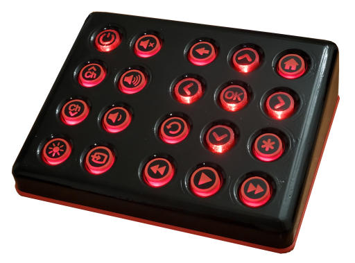
Dimensions: 222mm x 174mm x 65mm
Battery Life: 36-216 hours
Control Range: 100m
Cost: ~$96.00
Assembly Time: 3.5 hrs
3D Print Time: 25 hrs
You can find the BOM in the Keyboard Hardware Readme.
Keyboard Enclosure
Since this part takes the longest it is placed first.
Keyboard Hardware
Review the Keyboard Hardware Readme for an overview of the parts and schematics.
Equipment Needed:
- Soldering Iron
- Solder
- Wire Cutters
- Magnification Equipment
- Fine point ESD tweezers
Keyboard Assembly:
- Preform the ESP32 Thing Power Saving Modification as described in the Hardware Readme.
- Solder on all of the other components on the PCB.
- Cut the excess leads of the bottom side of the board, save enough of them to use to help solder the ESP32 Thing to the PCB.
- Attach the ESP32 Thing on the PCB temporarily secure with two nuts and bolts through the mounting holes near the micro USB port. Make sure all of the pins are aligned before tightening the bolts. Don’t over tighten.
- Place the PCD face down with bottom side up.
- Using the excess leads you saved from earlier, put a 90 degree bend in them and set them in each remaining pin on the PCB for the ESP32 Thing.
- Solder all of these to the board, and then trim the excess with the wire cutters.
- Flip the PCB over and solder the other end of the leads to the pins on the ESP32 Thing.
- Cut off the excess leads.
Keyboard Firmware
Equipment Needed:
- Any computer that can run the Arduino IDE
- A micro USB cable
- Adjustable Power Supply or 3.6V voltage source
We decided to use the arduino IDE to program the keyboard. To begin ensure you have the necessary applications and drivers installed as described in the Sparkfun ESP32 Thing Plus Hookup Guide - Sofware Setup for more details.
If you haven’t already download any of the dependent libraries mentioned in the sketch before trying to compile and upload.
Also, be sure to add the MAC address you saved from the IR blaster to the ‘BRODCAST_ADDR’ constant at the begining of the sketch.
Once finished you will need to calibrade the battery read function before final assembly.
Battery Read Calibration:
- Attach a 3.6V source to the battery terminal on the keyboard PCB.
- Press and hold the pin 0 button on the ESP32 thing for 2 seconds until the backlight LEDs start flashing.
- The keyboard backlight LED’s will flash 5 times indicating that it has calculated and saved the battery analog read offset.
Keyboard Final Assembly
Equipment Needed:
- Phillips Screw Driver
- Strong double sided adhesive
Final Assembly:
- Place the PCB in the the enclosure and secure in place with screws.
- Use some double sided adhesive tape to tape the battery to the base of the enclosure.
- Plug in the battery to the bottom of the PCB.
- Place the base of the enclosure over the main enclosure and secure with screws.
- Firmly push all of the buttons onto the keys until they are securely in place. Be sure to align them so that the narrows part of the button shaft matches the narrowest part of the key stem.
- Using a cutting machine cut the button decals out off black vinyl.
- Apply the vinyl decals to the buttons.